The Importance of Polarity : An understanding of polarity is essential to correctly construct three-phase transformer banks and to properly parallel single or three-phase transformers with existing electrical systems. A knowledge of polarity is also required to connect potential and current transformers to power metering devices and protective relays. The basic theory of additive and subtractive polarity is the underlying principle used in step voltage regulators where the series winding of an autotransformer is connected to either buck or boost the applied line voltage.
Transformer Polarity refers to the relative direction of the induced voltages between the high voltage terminals and the low voltage terminals. During the AC half-cycle when the applied voltage (or current in the case of a current transformer) is from H1 to H2 the secondary induced voltage direction will be from X1 to X2. In practice, Polarity refers to
the way the leads are brought out of the transformer.
Bushing Arrangement: The position of the High Voltage Bushings is standardized on all power and instrument transformers.
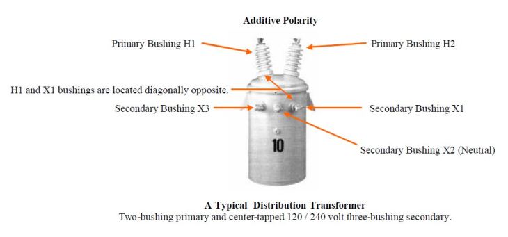
The rule is this: when facing the low voltage bushings, the Primary Bushing H1 is always on the left-hand side and the Primary Bushing H2 is on the right-hand side (if the transformer is a three-phase unit, H3 will be to the right ofH2).
Distribution Transformers are Additive Polarity and the H1 and X1 bushings are physically placed diagonally opposite to each other. Since H1 is always on the left, X1 will be on the right-hand side of a distribution transformer. This standard was developed very early in the development of electrical distribution systems and has been adhered to in order to prevent confusion in the field when transformers need to be replaced or paralleled with existing equipment.
In situations where the secondary bushing identification is not available or when a transformer has been rewound, it may be necessary to determine the transformer polarity by test. The following procedure can be used :
- The H1 (left-hand) primary bushing and the left-hand secondary bushing are temporarily jumpered together and a test voltage is applied to the transformer primary. The resultant voltage is measured between the right-hand bushings. If the measured voltage is greater than the applied voltage, the transformer is Additive Polarity because the polarity is such that the secondary voltage is being added to the applied primary voltage. If, however, the measured voltage across the right-hand bushings is less than the applied primary voltage, the transformer is Subtractive Polarity.
Note: For safety and to avoid the possibility of damaging the secondary insulation, the test voltage applied to the primary should be at a reduced voltage and should not exceed the rated secondary voltage.

In the figure shown above, if the transformer is actually rated 480 – 120 volts, the transformer ratio is 4:1 (480 / 120 = 4).
Applying a test voltage of 120 volts to the primary will result in a secondary voltage of 30 volts (120 / 4 = 30). If transformer is subtractive polarity, the voltmeter will read 90 volts (120 – 30 = 90). If the voltmeter reads 150 volts, the transformer is additive polarity (120 + 30 = 150). The red arrows indicate the relative magnitude and direction of the primary and secondary voltages.


HELLO
hello parveen… 🙂
Dear sir
please i want full of vector group char and with voltage conditons its help my company. i am gangadhar from Trafomec india p ltd bangalore.
visit the link given below…
https://electricalnotes.wordpress.com/2012/05/23/vector-group-of-transformer/